Capture Moving Objects
Overview
This solution demonstrates how to utilize a PIR sensor to achieve intelligent motion detection and automatic capture functionality, providing a low-power solution for scenarios such as security monitoring and smart homes.
Technical Background
Passive Infrared Sensor (PIR) detects motion by sensing changes in infrared radiation. Key technical features include:
- Detection Range: 3-7 meters (depending on the specific model)
- Detection Angle: 110° horizontal × 90° vertical wide-angle coverage
- Power Characteristics: Operates at 3.3V-5V
- Energy Efficiency: Ultra-low standby power consumption, ideal for battery-powered devices
Development Preparation
Hardware Configuration
- Main Control Unit: ESP32-S3 core development board
- Sensor Module: PIR motion detection sensor
- Power Supply System: Lithium battery pack (optional)
Software Resources
1. Quick Deployment Firmware
- Precompiled production firmware download: PIR Detection Firmware
2. Development Environment Configuration
- Development Tool: Visual Studio Code (v1.99.2+)
- Development Framework: ESP-IDF plugin (v5.1.6)
- Sample Code Repository: lowpower_camera
Function Verification
Precompiled Firmware Usage Guide
1. Hardware Connection
- Connect the PIR sensor to the specified interface on the development board.
- Ensure a stable power supply.
For detailed wiring instructions, refer to: Hardware Connection Guide
2. Firmware Flashing
Follow the standard flashing process: System Flashing and Initialization Guide
3. Function Testing
- Power on the device and complete initialization.
- Enter low-power standby mode.
- Trigger the PIR sensor:
- Observe the status indicator light response.
- Verify the automatic capture and upload functionality.
For the complete testing process, refer to: Quick Start Guide
Source Code Development Verification Process
1. Obtain the Code Repository
git clone https://github.com/camthink-ai/lowpower_camera.git
2. Project Configuration
Open the project directory with VS Code:

3. Key Configuration Items
- GPIO Settings:
- Use RTC GPIO to support wake-up functionality.
- Avoid external pull-up interference.

- Sensitivity Adjustment:
- Adjust detection parameters based on the application scenario.

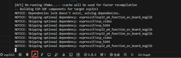
4. Compilation and Deployment
- Select the ESP32-S3 target chip:
![]()
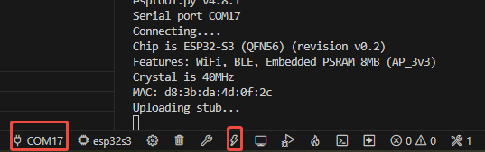
- Execute project compilation:
- Flash the generated firmware:
5. Function Verification
The testing method is the same as for the precompiled firmware.
Optimization Suggestions
Power Management Strategy
- Set a reasonable trigger interval (recommended ≥ 30 seconds).
Anti-Interference Measures
- Increase the PULSE_C parameter value (recommended 2-3 seconds).
- Keep away from motors, inverters, and other sources of interference.
Environmental Adaptation Suggestions
- Recommended installation height: 1.5-2 meters.
- Avoid direct sunlight on the sensor window.
- Regularly clean the sensor lens.
- Adjust the detection angle according to the scenario.
Debugging Tips:
- Use a logic analyzer to monitor GPIO signals.
- Analyze serial logs to identify the causes of false triggers.